|
TH-2 XPR Software Support
"UM" - 5x8 Universal Mixer Software
"UM" - TH-2 XPR Universal Mixing Software
Creating your own custom
mixing application is easy. Download the tutorials below.
TH-2 XPR
UM
Software Users Guide
Topic Index
UM
Control Software Specifications
Radio Settings
UM
Control Software General Information
Software Control Settings
UM Control Software Specifications
The UM-XPR-1 software implements a
Universal 5x8 mixer. Many types of mixing applications can be
created with this software such as single and multiple CCPM swash
plates mixing, drone control mixing,
VTOL type aircraft and more.
Each of the five (5) inputs can be mixed to
any of the eight (8) outputs. The gain of each mix can be set
to +/- 0% to 100% to accommodate any direction/polarity.
The mixer software offers two (2) mixing channels "heli" and
"airplane" selectable by the X input in switched mode,
Master mix mode = Switched.
The switching point is adjustable from 0% to 100%. When set to 101%
the heli gains are selected full time.
There is also a blended mode in which the "heli" and "airplane"
channels are blended linearly by the X input.
The outputs are the summation of H and A channels. The H channels
are blended by a gain of (X - 100) and the
A channels are blended by a gain of X.
The blended mode could be applied to a V22 type aircraft where
there is a need for both helicopter and airplane
controls and the blending provides a smooth transition between the
two flight modes.
Each of the eight outputs has five H-Mode gain inputs and five
A-Mode gain inputs.
Version: UM-XPR-1
| Number of
servo outputs |
8 |
|
|
| Servo
reversing |
All 8 outputs |
|
|
| Servo
centering |
All 8 outputs
with +/- 12.5% travel |
|
|
| Mixing
channels |
2, H-mode and
A-mode; Selected by X-input 0..100%; Also H-mode fixed |
|
|
| Mixing
modes |
2, Switched
and Blended |
|
|
| Required
inputs |
1, Pitch
Note: A gyro must not be used on the pitch input. |
|
|
| Optional
inputs |
Aileron,
Elevator, Rudder, Pitch, X ( for switching or blending) |
|
|
Input gain
control
internal |
5, Aileron,
Elevator, Rudder, Pitch, CH5 with 0 to 100% range
|
|
|
Input gain
control
external |
5, PT1..PT4
and the X input with 0 to 100% range |
|
|
|
|
|
|
Note: The X input will be
available for general external gain control if it is not used as a
switching/blending control.
To use the X input for
external gain control:
Set the Master Mix Mode to switched
.
Set the H/A Mode Switch Point to 101 (H-mode
gains selected full time (fixed))
There may be an application where the X input could be used as both
a switching/blending control and an
external gain control. Be
sure you fully understand these functions to avoid unexpected
results.
Radio Settings
This section describes what the settings
in your transmitter should be.
In general, start off with the servo travel (travel volume, end
point, etc.) set to 100% for aileron, elevator, rudder, pitch and
CH5.
This will give you a good starting point. Servo reversing will
depend on how you installed your servos and the brand as well.
All CCPM swashplate mixing must be turned off in the Tx.
Initially, all other mixing functions should be turned off as well.
After you have things working, you can then add programmable mixes
done by the TX.
UM Control Software General Information
- The TH-2 synchronizes with the pitch
channel (CH-6 on most radios) and expects it to be the last pulse
(that it "sees") in the data frame sent by the transmitter. Also,
A gyro should not be used on this channel.
- When setting up the DCP it helps to turn
off any cyclic component of that function to visualize it better.
This can
be done by temporarily setting the input gain to zero (0) in the Tech
Link modify settings menu.
-
When an input gain
is set to 100% the pulse data from the TX is used as is and mixed.
At 50%, the pulse
data from the TX is cut in half and then mixed and so on.
Reducing the gain in the TH-2 when needed,
like for DCP, is better than doing it in the TX (ATV setting)
since this would reduce the overall dynamic range.
-
The gain settings
also allow you to balance the amount of servo travel from the
contributing channels and
prevents clamping. The TH-2 is set to clamp at 0.90 ms min. and
2.10 ms max. to prevent servo damage
in the event of interference.
Software Control Settings
The TH-2 XPR UM Control Software uses
control settings as programmable parameters to allow customization
for many different applications and model types. These control
settings can be modified, loaded, saved and shared
with other users using our Tech Link software. Details of the
control settings are listed below.
Servo Reversing
Modify Settings - 1
Functions:
- Set servo direction normal/reverse.
Each of the eight servo outputs can be
reversed individually.
This function works in addition to the reversing done in the transmitter.
Here the individual servos are reversed. In the Tx, reversing
changes the control function direction.
Click on a box to select.
Servo Centering
Modify Settings - 2..9
2 - Servo Centering Front Ep
Output
3 - Servo Centering Front A Output
4 - Servo Centering Front E Output
5 - Servo Centering Front P Output
6 - Servo Centering Rear Ep Output
7 - Servo Centering Rear A Output
8 - Servo Centering Rear E Output
9 - Servo Centering Rear P Output
Functions:
- Set servo centering position
-12.5..12.5 percent (-125 ...125 microseconds)
Each servo output center (servo neutral
position) can be adjusted by+/- 12.5 percent.
This function works similarly to sub-trims in the transmitter.
Click on an arrow button or drag the slider to change.
H/A Mode Switch Point
Modify Settings - 10
Functions:
- Selects the switch point from H-mode
to A-mode mixing channel using the X input
H-mode is selected when X < Switch Point
A-mode is selected when X >= Switch Point
- The switching point is adjustable
from 0% to 100%
- Set to 101% to stay in H-mode
regardless of X-input (H-mode fixed)
Note: The X input range is clamped by the
software internally to values of 0 to 100.
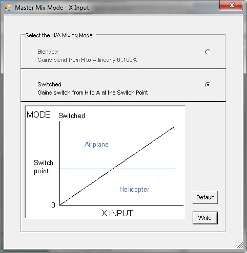
Master Mix Mode
Modify Settings - 11
Functions:
- Selects Blended or Switched
mixing mode
Switched mode
The two (2) mixing channels "heli" and "airplane" are selected by the X
input in switched mode,
The switching point is adjustable from 0% to 100%. When set to 101% the
H-mode gains are selected full time (fixed).
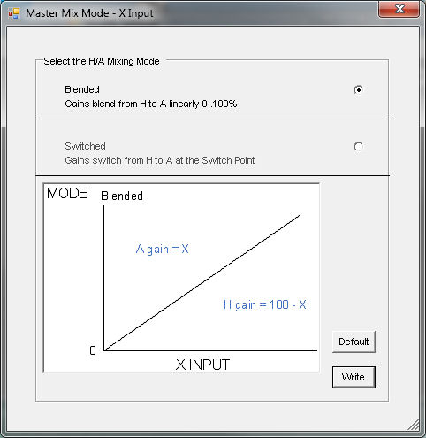
Blended mode
The two (2) mixing channels "heli" and "airplane" channels are blended
linearly by the X input.
The outputs are the summation of H and A channels. The H channels are
blended by a gain of (X - 100) and the
A channels are blended by a gain of X.
Note: The X input range is clamped by the software internally to values of
0 to 100.
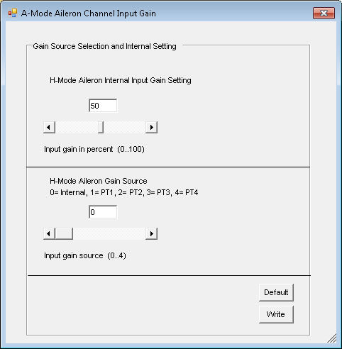
H-Mode Input Gains
Modify Settings - 12..16
12 H-Mode Aileron Channel Input Gain
13 H-Mode Elevator Channel Input Gain
14 H-Mode Rudder Channel Input Gain
15 H-Mode Pitch Channel Input Gain
16 H-Mode CH5 Channel Input Gain
Functions:
- Adjust internal gain 0..100
percent
- Select gain source
The input gain source can be selected as
internal or to one of the external sources - PT1..PT4 or the X input.
The internal setting is only active when the source is set to internal.
Internal gain settings can only be set via USB with Tech-Link.
Note: One or more input gains can be set to the same external gain source
(shared).
It is your choice on how to assign them. Write down your settings
for use when away from the PC.
For this software, all five external gains have a positive range of 0..100
percent.
Note: The dialog window below is one example of the five (5) H-mode
input gain settings.
A-Mode Input Gains
Modify Settings - 17..21
17 A-Mode Aileron Channel Input Gain
18 A-Mode Elevator Channel Input Gain
19 A-Mode Rudder Channel Input Gain
20 A-Mode Pitch Channel Input Gain
21 A-Mode CH5 Channel Input Gain
Functions:
- Adjust internal gain 0..100
percent
- Select gain source
The input gain source can be selected as
internal or to one of the external sources - PT1..PT4 or the X input.
The internal setting is only active when the source is set to internal.
Internal gain settings can only be set via USB with Tech-Link.
Note: One or more input gains can be set to the same external gain source
(shared).
It is your choice on how to assign them. Write down your settings
for use when away from the PC.
For this software, all five external gains have a positive range of 0..100
percent.
Note: The dialog window below is one example of the five (5) A-mode
input gain settings.
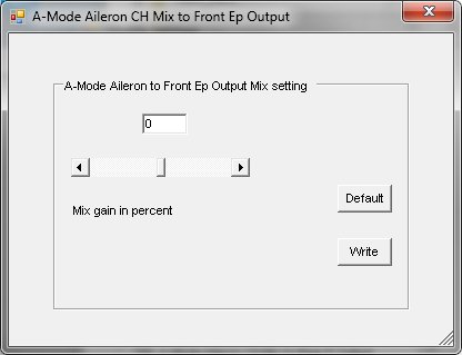
H-Mode Mixing Channels
Modify Settings - 22..61
Functions:
- Adjust Input to Output mixing gain
-100 to +100
percent
These settings determine the mixing between
the inputs to the outputs.
Note: The dialog window below is one example of forty (40) H-mode
mixing channel settings.
| |
|
|
| |
 |
|
| |
|
|
22 H-Mode Aileron CH Mix to Front Ep
Output
23 H-Mode Aileron CH Mix to Front A Output
24 H-Mode Aileron CH Mix to Front E Output
25 H-Mode Aileron CH Mix to Front P Output
26 H-Mode Aileron CH Mix to Rear Ep Output
27 H-Mode Aileron CH Mix to Rear A Output
28 H-Mode Aileron CH Mix to Rear E Output
29 H-Mode Aileron CH Mix to Rear P Output
30 H-Mode Elevator CH Mix to Front Ep Output
31 H-Mode Elevator CH Mix to Front A Output
32 H-Mode Elevator CH Mix to Front E Output
33 H-Mode Elevator CH Mix to Front P Output
34 H-Mode Elevator CH Mix to Rear Ep Output
35 H-Mode Elevator CH Mix to Rear A Output
36 H-Mode Elevator CH Mix to Rear E Output
37 H-Mode Elevator CH Mix to Rear P Output
38 H-Mode Pitch CH Mix to Front Ep Output
39 H-Mode Pitch CH Mix to Front A Output
40 H-Mode Pitch CH Mix to Front E Output
41 H-Mode Pitch CH Mix to Front P Output
42 H-Mode Pitch CH Mix to Rear Ep Output
43 H-Mode Pitch CH Mix to Rear A Output
44 H-Mode Pitch CH Mix to Rear E Output
45 H-Mode Pitch CH Mix to Rear P Output
46 H-Mode Rudder CH Mix to Front Ep Output
47 H-Mode Rudder CH Mix to Front A Output
48 H-Mode Rudder CH Mix to Front E Output
49 H-Mode Rudder CH Mix to Front P Output
50 H-Mode Rudder CH Mix to Rear Ep Output
51 H-Mode Rudder CH Mix to Rear A Output
52 H-Mode Rudder CH Mix to Rear E Output
53 H-Mode Rudder CH Mix to Rear P Output
54 H-Mode CH5 CH Mix to Front Ep Output
55 H-Mode CH5 CH Mix to Front A Output
56 H-Mode CH5 CH Mix to Front E Output
57 H-Mode CH5 CH Mix to Front P Output
58 H-Mode CH5 CH Mix to Rear Ep Output
59 H-Mode CH5 CH Mix to Rear A Output
60 H-Mode CH5 CH Mix to Rear E Output
61 H-Mode CH5 CH Mix to Rear P Output
A-Mode Mixing Channels
Modify Settings - 62..101
Functions:
- Adjust Input to Output mixing gain
-100 to +100
percent
These settings determine the mixing between
the inputs to the outputs.
Note: The dialog window below is one example of forty (40) A-Mode
mixing channel settings.
| |
|
|
| |
 |
|
| |
|
|
62 A-Mode Aileron CH Mix to Front Ep Output
63 A-Mode Aileron CH Mix to Front A Output
64 A-Mode Aileron CH Mix to Front E Output
65 A-Mode Aileron CH Mix to Front P Output
66 A-Mode Aileron CH Mix to Rear Ep Output
67 A-Mode Aileron CH Mix to Rear A Output
68 A-Mode Aileron CH Mix to Rear E Output
69 A-Mode Aileron CH Mix to Rear P Output
70 A-Mode Elevator CH Mix to Front Ep Output
71 A-Mode Elevator CH Mix to Front A Output
72 A-Mode Elevator CH Mix to Front E Output
73 A-Mode Elevator CH Mix to Front P Output
74 A-Mode Elevator CH Mix to Rear Ep Output
75 A-Mode Elevator CH Mix to Rear A Output
76 A-Mode Elevator CH Mix to Rear E Output
77 A-Mode Elevator CH Mix to Rear P Output
78 A-Mode Pitch CH Mix to Front Ep Output
79 A-Mode Pitch CH Mix to Front A Output
80 A-Mode Pitch CH Mix to Front E Output
81 A-Mode Pitch CH Mix to Front P Output
82 A-Mode Pitch CH Mix to Rear Ep Output
83 A-Mode Pitch CH Mix to Rear A Output
84 A-Mode Pitch CH Mix to Rear E Output
85 A-Mode Pitch CH Mix to Rear P Output
86 A-Mode Rudder CH Mix to Front Ep Output
87 A-Mode Rudder CH Mix to Front A Output
88 A-Mode Rudder CH Mix to Front E Output
89 A-Mode Rudder CH Mix to Front P Output
90 A-Mode Rudder CH Mix to Rear Ep Output
91 A-Mode Rudder CH Mix to Rear A Output
92 A-Mode Rudder CH Mix to Rear E Output
93 A-Mode Rudder CH Mix to Rear P Output
94 A-Mode CH5 CH Mix to Front Ep Output
95 A-Mode CH5 CH Mix to Front A Output
96 A-Mode CH5 CH Mix to Front E Output
97 A-Mode CH5 CH Mix to Front P Output
98 A-Mode CH5 CH Mix to Rear Ep Output
99 A-Mode CH5 CH Mix to Rear A Output
100 A-Mode CH5 CH Mix to Rear E Output
101 A-Mode CH5 CH Mix to Rear P Output
Copyright © 2019 by Tech Model
Products LLC. • All Rights Reserved |